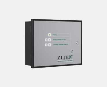
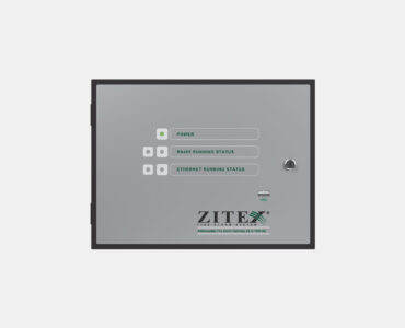
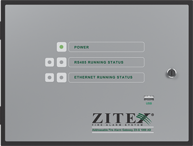
Addressable Gateway

ZX-G 1000 AD

To control and monitor the performance of ZITEX addressable systems online and remotely, a device called Addressable fire alarm Gateway has been designed and built. This device is placed as part of the RS485 network next to other panels and repeaters and is connected to this network through LAN (wired or via WIFI network). The device has a separate and independent power source/charger (two back-up batteries are responsible for powering the device in case of main power failure). After establishing a connection between the Gateway device and the RS485 network, through the graphic computer software, it is possible to do the following:
Viewing the online status of devices and panels
View History Log of all panels online
Software update of all networked panels
Backup of configuration parameters of networked panels
Gateway device settings can be done in two ways. By default, the connection to the LAN network is done through DHCP, but in some cases, customers may request to define a static IP address, for which a special software has been designed and created.
SCRIPT FOR SLIDER CAROUSEL

Addressable Control Panel

ZX-G 1000 AD


  • Automatic addressing of all devices from the panel
  • ZITEX specialized and exclusive protocol
  • Hardware lock (dongle) and password for integrated protection at access level 4 to prevent system manipulation by irresponsible people
  • Networking of 32 panels or repeaters based on RS485 protocol with internal network card without the need for additional cards
  • Automatically address and register 32 panels or networked repeaters within 1 minute
  • Control and identify cabling defects and determine the exact location within the network
  • Control and identification of cabling defects and determining the exact location of cabling outages inside the loop
  • 32 km coverage with 32 grid panels or repeaters 1 km apart
  • Control and monitor panels or repeaters networked with any panel or repeater within the network
  • Software and hardware control technology to eliminate false noise and alarms
  • Separate and independent addressing or simultaneous loops
  • Addressing 1000 devices in 4 loops in less than 30 minutes
  • Free access to all startup software, calculators and updates
  • Double-sided loop to supply voltage to the devices from both sides of the loop card in certain cases
  • Save 10,000 events with full details, no time limit
  • Print event logs via printer or copy using USB as a .txt file
  • Black box technology for storing the last 500 events indelibly in the panel memory in case of intentional or accidental deletion of events (access and retrieval only through the factory)


  • Two-way communication between panels and devices to make changes to devices and monitor their instant scheduling
  • Update motherboard, loop baseboard and repeater software via U-disk without the need to connect a cable to a computer
  • Modular structure of boards and panel loops and the possibility of upgrading from one to four loops for each panel
  • Ability to add a portable printer on the panel
  • 96 programmable zones for 1 to 4 loops
  • Capacity of 250 devices per loop (twice the capacity of standard installation requirements)
  • Cover a distance of 1000 meters per loop
  • Physical protection with second door projection
  • Set time for notification in order to conduct periodic visits
  • Identify devices and their location in the loop
  • Securely store addresses and configuration information on the base loop and protect against deleting this information if the loop card is replaced
  • System health status report (voltage and current consumption of motherboard, loop cards, external relays, main power supply and backup panel)
  • Activation and monitoring of various inputs and outputs such as exhaust fans, dampers, positive pressure fans, extinguishing scenarios, emergency outlets and other peripherals using input-output modules and relays embedded on the panel


  • Predict short circuit protection circuit for power board and panel
  • Protection against the effects of electromagnetic fields and electric and electronic shocks in all circuits
  • Grouping devices and zoning and performing all control and reporting operations without the need for a direct connection to the computer through the panel itself or through the configuration software at access level 4
  • Define and program system outputs such as sirens and side relays through access level 4 panel or through configuration software
  • Define and program the status of input-output modules and conventional zone modules on the loop through the panel at access level 4 or through the configuration software
  • Ability to define latency for panel outputs
  • Ability to define day and night modes to change the sensitivity and class of detectors
  • Graphic table showing devices based on type and status in the relevant menu
  • View online streams and alarms on all devices and entire system loops
  • Ability to disable the desired devices, zones and loops
  • Engineering testing of sending and receiving data and identification of communication problems in this process
  • Rename devices and zones through the panel or configuration software
  • Three modes to activate the zone output: normal mode, two devices of one type and two devices of two different types
  • Ability to change the address of devices
  • Ability to add a new device to the loop and assign the address separately
  • Two outputs for conventional siren in addition to loop power sirens with the possibility of installing 10 sirens for each output


  • Set sirens in both Zonal and Common modes for alarm and discharge modes
  • Setup without the need for a license and connection to a computer
  • Professional engineering design, standard materials, ABS heat, shock and vibration resistant
  • Ability to install surface and built-in
  • Wiring glands and corridors for easy and principled installation
  • Specialized power supply to prevent damage due to voltage fluctuations
  • Use of socket terminals and allocate enough space to set up the system
  • Double-layer metallized fiberglass circuit with moisture, vapor and corrosion resistant layer
  • Production of electronic boards using modern equipment based on SMT technology
  • Specialized programming
  • 6-inch screen with 10 lines of 40 characters to view all errors, alarms and other events in full
  • LAN and BMS output to connect to graphic software for controlling devices and building management system via gateway
  • Manual programmer for manually addressing devices when adding new devices to the loop or reading the addresses of devices installed inside the loop without the need to use a panel
  • Current leak test technology to identify the exact location of current leakage in the wiring system
  • Has the mark of the national standard of Iran and conforms to the international standard EN 54-2


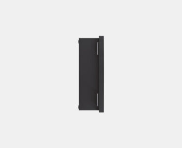
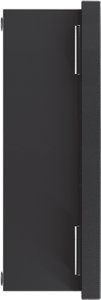
Product Size

گیت وی آدرس پذیر ZX-G 1000 AD زیتکس

<        8 CM        >

گیت وی آدرس پذیر ZX-G 1000 AD

<        28.4 CM        >

Technical Specifications ZX-P 1000 AD
Supply voltage 230 V A.C (-15%_+10%), 50/60 Hz
System voltage 20-30 V D.C.
Zone indicator (LED) 96 PCS
Output Fault 1 relay (24 V D.C) 3 A
Output Fire 1 relay (24 V D.C) 3 A
Output Alarm 2 lines, each line: 24 V
Battery required 2 x 12 V, 7.2 Ah
Degree of protection IP 30
Functional temperature -10 °C — +50 °C
Functional humidity (Non-condensing) 5% — 95% RH
Printer Optional
Dimensions 510 x 390 x 110 mm
Number of loops 4 3 2 1
Loop capacity (number of parts) 4 x 250 3 x 250 2 x 250 1 x 250
Standard requirement EN 54-2 Installation of more than 512 detectors or callpoints in a non-standard panel
Weight without battery 8.8 Kg
zitex-search-icon
Follow US
کد آیکون
zitex-search-icon
All Rights Reseved By Arman Imen Iranian Company (ZITEX Co).
.